Testing Procedures
Testing for the architectural model began at the Technology Student Association competition on April 15, 2008. The completed architectural model and design notebook including schedules, floor plans, and other related architectural drawings were submitted to the competition to be evaluated by several judges. Evaluation was based on points earned for the notebook and architectural model. After the competition a picture was taken of the model on a level surface to depict its realism. A survey was also developed to receive feedback from twenty-five students in Systems Engineering II. Each question was answered on a scale of one to ten (ten being the best). See attached surveys.
Test Results
Test results will be completed when twenty-five surveys have been filled out. After this task is completed I will be taking averages of every question and developing a bar graph to display the overall results of the survey. So far the surveys have been receiving good ratings. Please refer to surveys for students’ answers and comments.
The design of my architectural drawings and model meet the original criteria set by the Technology Student Association Architectural Model competition. The house was designed for a family of six including two grandparents. The design also follows the principles and guidelines established for the development of affordable housing in America. The total area of living space in the final solution came out to 1,609.5 feet squared. This area includes all rooms, hallways, walls, etc. (except the garage). The total area was then multiplied by $110 per feet squared and a price of $177,045 was obtained. This number represents an estimate cost to build the living space of the house. The total area of the garage including the walls came out to 517.5 feet squared. This total area was then multiplied by $50 per feet squared and a price of $25,875 was obtained. This number represents an estimate cost to build the garage space of the house.
The model was also placed on a site board of the correct size and was built to a scale (1/4” = 1’-0”), which is commonly used by most architects. The design notebook includes everything that was required and was arranged in the correct order. The first page includes a description of the styles and merits of the design concepts. The second page is comprised of a schedule of finish materials for all exterior and interior surfaces of the architectural design. The following were required reproduction copies of printer generated CAD drawings: Original floor plans, sectional detail drawing, foundation plan, roof plan, and a landscape plan. Please refer to the design notebook to see these architectural drawings.
Thursday, May 29, 2008
Self and Design Evaluation
Introduction
The need to design and construct affordable housing in America is urgent. Twenty-five percent of all American households face severe housing problems. Among these are lack of sufficient funds for monthly payments, maintenance, and repairs; overcrowding, both within individual dwellings and in high-density multi-family developments; and structural deficiencies.
These 30 million households include not just the poorest individuals and those without jobs, but also teachers, librarians, firefighters, health-care workers, and many others who make significant contributions to our communities.
According to the U.S. Department of Housing and Urban Development, the generally accepted criteria of affordability is that a household pays no more than 30% of its annual income on housing. In many localities across America, an increasing number of families are earning less than 50% of the median income in their respective area, assuming they spend no more than 30% of their income for housing.
Research was conducted on the guidelines established for affordable housing. After sufficient information was collected, brainstorming for a single family home for a family of six including an aging set of grandparents began. Several floor plans were drawn and finalized, and one solution was chosen for further development. An architectural model was then constructed based off of the final floor plans. An understanding and aptitude for the process of architectural design, development of plans, and basic modeling techniques was demonstrated throughout the course of the project.
Solution Description
The chosen solution featured a three-bedroom house. A covered porch opens up into a foyer, compensated by a convenient closet. The entry from the garage into the house is a mudroom like the previous alternate solution. The kitchen features a small pantry and contains an opening in the wall to serve food and drinks to the gathering and dining room. The dining room is easily accessible from the kitchen. In the back of the house is the gathering room with an ample amount of space.
From the gathering room, a large hallway leads to the children’s bedroom and the master bedroom. The master bedroom’s main aspect is its large walk-in closet and bathroom. The best feature of this alternate solution is that the grandparent’s living quarters because they are located away from the rest of the family, giving them a feeling of living on their own. They can easily access the bathroom and have their own living room and miniature kitchen. The living room leads into a separate bedroom and overall gives the grandparents plenty of space. All in all, this solution has proved to be the most viable because of the interconnection of similar rooms and how the layout flows.
Discrepancies Between Original Design and Final Constructed Solution
The original design was further developed into an Auto-CAD drawing. The floor plan has several modifications in order to maximize the effective of the flow and use of space. The foyer has been made slightly smaller and a half bathroom has been added on the left side. A mechanical/storage room and a mudroom have been placed directly behind the garage. Also, a small pantry has been added near the kitchen. The dining room and living room have been sized down keeping in mind affordable housing. Also the wall that separates these two rooms no longer has a column in the center. The island in the kitchen is now more easily accessible to the dining room.
As for the living section of the house, one more bedroom has been added to allow the children to have separate rooms. A bathroom has been placed conveniently and has two doors so that both the children and grandparents can easily obtain entry. The master bedroom has been sized down slightly and now contains two smaller closets instead of one walk-in closet. The bathroom has also been rearranged in size and layout to allow more walking space. The shower and bathtub were combined to reduce space used as well. Finally the main feature of the house was left virtually the same. The grandparents’ room still features a living room, small kitchen, and a separate bedroom. Overall this design has proved to be very effective in making use of space and keeping related rooms near one another.
Successes and Failures (Design Flaws)
During the course of the project, I succeeded in many areas. My design notebook, including the floor plans, elevational plans, roof plan, landscape plan, and sectional detail were completed with preciseness and in an orderly fashion. The window, door, and room finish schedules were also completed thoroughly. All drawings were done to scale, and this carried through with the model as well. All of the pieces were cut out accurately and placed in the correct positions. All parts of the balsa wood construction are even and smooth. The roof receives the best comments, and I believe it is the strongest part of the model. Although the grass has a few square patches, the landscaping have a very realistic look and adds to the professionalism of the model.
After the survey was conducted, positive results were received in all areas. I believe that the only failure during all phases of the project was not placing in the 2008 Technology Student Association Architectural Model Competition. The only thing that I can take away from this is that in order to have the best model, more time must be dedicated to its construction, rather than the drawings of the chosen solution.
Although I would not consider them failures, a few design flaws in the procedure of construction and the actual construction of the preliminary model were present. I thought about all of the improvements I could make upon the first model and integrated them into the final model. Some of these flaws included using Elmer’s glue instead of hot glue, sanding down all surfaces to be smooth and even, and placing down balsa wood pieces more carefully in the correct positions. Other flaws can be seen in my original drawings, including door placement and door size. However, the flaws were easily corrected with the help of my mentor
Additional Learning
I am grateful that I had a mentor through out the process of the project. I have learned many things that I would not have necessarily learned until college. Whenever I had any problems, my mentor was easily accessible and helped me out through emails or meeting in person. Any flaws in my drawings were easily corrected. My mentor also shared his advice that I willingly implemented into my drawings, he explained how to do things that I was unsure about, and taught me the basics of architectural model construction. One of the most important things that I learned was attention to detail. My mentor told me that it is important to have an accurate and neat model more than anything.
Personal Improvements
Problem Solving Skills: This project highly increased my problem solving skills for obvious reasons. I was given rules and specifications to build an architectural model and had to abide by them throughout the design and construction of the architectural drawings and model. I believe that I succeeded in solving the problem to this competition. I designed a residential home that accommodated for a family of six including an aging set of grandparents and abided by the guidelines of affordable housing, by creating a one-story home and condensing space wherever possible.
Communication Skills through Drawing: My project entailed many architectural drawings using CAD software. I believe that I strengthened my communication skills through these CAD drawings when I shared them with my mentor, teachers, and peers. I was able to communicate with them my ideas by showing them what I had designed and then receiving feedback from them. I gathered their advice and incorporated it into the design if I felt necessary. My speaking and writing skills also improved through several formal and informal presentations discussing my project and also several technically written documents.
Organizational Skills: Throughout my life I have always been a very organized person. During this project, I harnessed this skill in order to be efficient as possible in my design and construction. Organizational skills also helped me to manage my time better. It was important to know the locations of all the materials that I used, and the procedure for model construction. Working in a station that was neat and had everything that I needed where I was working also helped.
Conclusion
Overall I have had great success with my project. With the help of mentor, teachers, and research I learned many new things about architecture, enhanced previous skills, and developed new skills. The architectural plans that I designed and the model that I constructed are accurate and have a professional appearance. I am glad that I chose this project because it is a great foreground for what I will be learning and doing when I attend the School of Architecture when I attend The New Jersey Institute of Technology this fall.
Thursday, April 24, 2008
Marking Period Four Calendar
April 27-May 3
• Calendar due Monday, April 28
• Contact Mentor
• Develop survey for testing architectural model
• Update Webblog
May 4-10
• Testing and Test Results due Thursday, May 8
• Update Webblog
May 11-17
• Self and Design Evaluation Assignment due Wednesday, May 14
• Update Webblog
May 18-24
• Architectural model exhibit due Tuesday, May 20
• Exhibit showcase on Thursday, May 22
• Update Webblog
May 25-31
• Formal Update on Wednesday, May 28
• Webblogs due Wednesday, May 28
June 1-7
• Mentor Contacts due Wednesday, May 4
June 8-14
• Systems Engineering II Final Exam on Tuesday, May 10
June 15-17
• School ends on Tuesday, June 17
Wednesday, April 2, 2008
Final Model Construction

Cutting balsa wood with an exacto knife
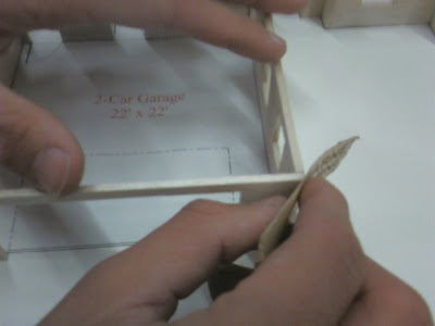
Sanding down balsa wood after it has been glued and set in place. Provides smooth finish and level walls.

Final model with all interior and exterior walls complete
 Another view of the model

Final model with roof under construction
Monday, February 4, 2008
MP3 Calendar
2/4 - 2/9
Develop marking period three calendar. Finalize landscape plan. Obtain materials for the final model. Contact mentor. Update WebBlog.
2/10 - 2/16
Begin construction of the final model. Contact mentor. Update WebBlog.
2/17 – 2/23
Continue construction of the final model. Contact mentor. Update WebBlog.
2/24 – 3/1
Continue construction of the final model. Contact mentor. Update WebBlog.
3/2 – 3/8
Continue construction of the final model. Contact mentor. Update WebBlog.
3/9 - 3/15
Continue construction of the final model. Contact mentor. Update WebBlog.
3/16 – 3/22
Continue construction of the final model. Contact mentor. Update WebBlog. Press release due 3/19.
3/23 - 3/29
Complete construction of the final model. Prepare for formal progress update. Make outline for presentation. Prepare mentor contacts. Contact mentor. Update WebBlog. Construction assignment.
3/30 - 4/5
Contact mentor. Update WebBlog. Formal progress update (presentation) on 4/2. Webfolio/Logs/Mentor contacts due 4/3.
4/6 – 4/10
Contact mentor. Update WebBlog. Marking period ends 4/10.
Thursday, January 17, 2008
Developmental Work
My senior project involves developing an extensive set of drawings that will assist me in constructing an architectural model for a family of six (including an aging set of grandparents). The major material that I will be using in construction is balsa wood. My model will be constructed on a foam-core board no larger than 24” square. Throughout the process, prior to and during construction, I will be receiving guidance from my mentor.
Supply List
1) Glue: Model material attachment
2) 3 Sandpaper Sheets (9” x 11”): Material reduction/ forming
3) (Color) Paint (10 Grams): Exterior wall finish
Tool and Equipment List
1)Exacto Knife: Cut out balsa wood
2)Back Saw/Hand Saw: Cut out balsa wood
Material List
1) 10 Balsa Wood Sheets (1/8” x 4” x 36”): Model
2) Foam-Core Board (24” x 24”): Model base
3) 10 Sandpaper Sheets (9” x 11”): Roof/Driveway
4) 1 Bag of Lichen (Spring Green): Grass (Applied to green paint)
Plan of Procedures
1. Glue floor plan (actual drawing) in the center of the model base.
2. Based on all drawings, cut out all exterior walls from balsa wood.
3. Glue exterior walls in place, directly on top of floor plan.
4. In order to not mix up any interior walls and waste material, glue pieces to the floor plan in a systematic order as soon as they are cut.
Note: Be sure to cut out all doors and windows from balsa wood before gluing to model base.
5. When all walls are in place, construct the roof as a separate attachment. Cut pieces out based on the length of each individual half of a gable roof. Glue pieces together based on the pitch and slope of the roof plan.
6. Cut slits into sandpaper based on the size of the shingles from drawings and glue the required amount to cover the surface of the roof.
7. Cut out pieces of balsa wood to form patio and glue to model base.
8. Cut out a separate sheet of sandpaper for the driveway and glue to model base.
9. Paint the rest of the model base green and sprinkle lichen on top. Remove excess when dry.
10. Paint exterior wall and patio according to colors in drawings.
CAD DRAWINGS
Floor Plan

Roof Plan

Northern Elevation

Eastern Elevation

Southern Elevation

Sectional Detail


Room Finish Schedule

Door Schedule

Window Schedule

Thursday, January 10, 2008
Math and Science Final Report
Math and Science Final Report
1. Introduction
The past several weeks have been dedicated to my developmental work for my final solution. I have been working on several drawings and created a basic model that will ultimately assist me in the construction of my final architectural model. These steps are necessary for the production of the final solution and will help me avoid mistakes as much as possible. Math, science, and technology strongly relate to my project. They will define my final solution and support my choice of solutions.
2. Science Concepts
a. Layout/Ergonomics/Flow
i. Overview
The final solution was chosen mainly because of the layout and usage of space. The flow between the rooms is based off of their relation to one another. Ergonomics, the science that deals with designing and arranging things that people use, played a huge role in the final solution. Since the design of the house must compensate for all residents, the house was mainly designed for the elderly to function properly if they had mobility impairments. For example, all door openings and hallways are three feet wide for convenient use by persons in wheelchairs.
The following will be an overview of the house and how the rooms interconnect for maximum efficiency. The floor plan of the final solution (Figure 1) can be viewed for guidance. The front porch allows access to both the main entrance of the house and the garage. Next to the foyer is a half-size bathroom and a closet for people to hang their coats as soon as they enter the house. The right side of the house features all of the bedrooms. The first room located next to they foyer is the grandparents living room/kitchen, which then leads to their bedroom. Their rooms are located towards the front of the house and away from the other bedrooms, to give them a sense that they are living on their own. The grandparents and children can easily access the Jack-and-Jill styled bathroom. The children’s bedrooms are symmetrical and located on the same hallway leading to the master bedroom. The master bedroom features two closets and a master bathroom.
The left side of the house starts with a two-car garage. In the back of the garage is a mechanical/storage room. Through the back of the garage is an entrance to the house with an open laundry/mud room on the right side. The kitchen features two side-entrances and a large island for serving and dining. A pantry is placed on the left side of the kitchen for easy access. Finally, the dining room and living room are divided by a half-wall with three columns to section off the rooms, and also to create a feel of open space.
 Figure 1: Floor Plan
ii. Traffic Areas and Patterns
Traffic areas of a house provide passage from one room or area to another. Efficient allocation of space was important when these areas were planned.
1. Entrances
The final solution has an outside waiting area (porch), a separation (door), and an inside waiting area (foyer). The main entrance is centrally located in order to provide easy access to the major areas of the house. The porch has a sufficient outside covered portion to shelter several people entering the house. A side entrance on the porch allows access to the garage. The foyer arrangement allows for the swing of all doors in the area and has enough space to allow several people to enter the house at the same time. The foyer closet is large enough for both family and guests to use for outdoor clothing. There is also a sliding door and a side door in side the house to allow convenient admittance outside.
2. Halls
The halls provide a controlled path that connect the various areas of the house and were designed to minimize traffic through rooms. All of the halls are three feet wide for furniture movement and wheelchair access. A half-wall divides the living room and dining room to channel hall traffic without the use of solid walls and two separate rooms.
ii. Living Room
The living room is one of the most important rooms in the house because it can serve many purposes. Since this project is designed under the affordable living guidelines, the room is on the smaller side, but should still allow for the combination of many living area activities. The room is easily accessible, but not visible, from the rest of the living area. It is located adjacent to the dining room so that it can become an extension of the room for social affairs. The separation between the two rooms with a half wall increases the connection between the two rooms.
iii. Dining Room
The purpose of a dining room is to provide a place for the family and guests to eat. Its ideal location requires only a few steps to get to and from the kitchen.
iv. Kitchen
The purpose of the kitchen is food preparation. The kitchens were designed to encompass space configuration, work surfaces, storage, and several components (refrigerator, stove, and dishwasher). The kitchen has four basic functions: storage, cooking, cleanup, and preparation. All of these functions are covered by the appliances, counter-tops, island, sink, cabinets, and refrigerator. Since space is limited, I decided to choose a combination of a u-shaped and corridor kitchen arrangement for the main house and an L-shaped kitchen for the grandparents.
v. Bedrooms
Since the competition’s specifications require a design for a family of six that includes an aging set of grandparents, a total of four bedrooms were chosen for the final solution. The primary function of a bedroom is to provide facilities for sleeping. All of the bedrooms are located on the right side of the house for sleeping comfort and privacy. As I stated earlier, the grandparents’ bedroom is still somewhat separate from the rest of the rooms to give them a sense of living on their own. The other three bedrooms are located off of the main hall of the house. Closets are located in each bedroom for storage space. A Jack-and-Jill bathroom is located to allow both the children and grandparents easy access. As in most houses, the master bedroom has an adjacent bathroom.
b. Structural Design
As with most modern buildings, the final solution has a skeleton-frame structure. Figure 2 displays the sectional detail of the final solution. The framework is open, self-supporting and covered by an outer, non bearing surface. The stability of the structure is based on the strength and placement of the structural members. The foundation was designed to support the loads of the structure while also keeping in mind that the structure must withstand the forces acting on it as well. The walls are given stability by their attachment to the ground and to the roof, while the roof is supported by the wall framework and interior partitions. The exterior wall is supported by the foundation, which is supported by full length footings. The footings distribute the heavy load of the structure throughout the surrounding ground and keep the entire structure firmly on the ground. Four types of forces that exert stress on building materials and the structure are compression, tension, shear, and torsion. All material in the structure based on size and location should be sufficiently strong and the stress created by these forces will create little or no damage. Figure 2:Sectional Detail
c. Strength of Materials
The strength of construction material is the material’s capacity to support loads by resisting compression, tension, shear, and torsion forces. The structural strength depends on the type, size, and shape of the material. The steel members and concrete slabs can support more weight than a wood member of the same size, and are placed in areas with heavy building loads. Figure 3 displays concrete slabs that make up the foundation of the structure.
d. Sills
The foundation sills for the structure are wood members that are fastened to the top of foundation walls and provide the base for attaching floor systems to foundations. Sheet-metal termite shields are placed between the wood and concrete. Figure 3 displays both the sill and the termite shield.
 Figure 3: Sill
e. Insulation
Insulation is used throughout the exterior walls in order to achieve thermal comfort for the occupants. It reduces unwanted heat loss or gain and addresses the main methods of heat transfer (conduction, radiation, and convection). Figure 4 displays a representation of insulation drawn in the sectional detail drawing.
 Figure 4: Insulation
1. Introduction
The past several weeks have been dedicated to my developmental work for my final solution. I have been working on several drawings and created a basic model that will ultimately assist me in the construction of my final architectural model. These steps are necessary for the production of the final solution and will help me avoid mistakes as much as possible. Math, science, and technology strongly relate to my project. They will define my final solution and support my choice of solutions.
2. Science Concepts
a. Layout/Ergonomics/Flow
i. Overview
The final solution was chosen mainly because of the layout and usage of space. The flow between the rooms is based off of their relation to one another. Ergonomics, the science that deals with designing and arranging things that people use, played a huge role in the final solution. Since the design of the house must compensate for all residents, the house was mainly designed for the elderly to function properly if they had mobility impairments. For example, all door openings and hallways are three feet wide for convenient use by persons in wheelchairs.
The following will be an overview of the house and how the rooms interconnect for maximum efficiency. The floor plan of the final solution (Figure 1) can be viewed for guidance. The front porch allows access to both the main entrance of the house and the garage. Next to the foyer is a half-size bathroom and a closet for people to hang their coats as soon as they enter the house. The right side of the house features all of the bedrooms. The first room located next to they foyer is the grandparents living room/kitchen, which then leads to their bedroom. Their rooms are located towards the front of the house and away from the other bedrooms, to give them a sense that they are living on their own. The grandparents and children can easily access the Jack-and-Jill styled bathroom. The children’s bedrooms are symmetrical and located on the same hallway leading to the master bedroom. The master bedroom features two closets and a master bathroom.
The left side of the house starts with a two-car garage. In the back of the garage is a mechanical/storage room. Through the back of the garage is an entrance to the house with an open laundry/mud room on the right side. The kitchen features two side-entrances and a large island for serving and dining. A pantry is placed on the left side of the kitchen for easy access. Finally, the dining room and living room are divided by a half-wall with three columns to section off the rooms, and also to create a feel of open space.
Figure 1: Floor Planii. Traffic Areas and Patterns
Traffic areas of a house provide passage from one room or area to another. Efficient allocation of space was important when these areas were planned.
1. Entrances
The final solution has an outside waiting area (porch), a separation (door), and an inside waiting area (foyer). The main entrance is centrally located in order to provide easy access to the major areas of the house. The porch has a sufficient outside covered portion to shelter several people entering the house. A side entrance on the porch allows access to the garage. The foyer arrangement allows for the swing of all doors in the area and has enough space to allow several people to enter the house at the same time. The foyer closet is large enough for both family and guests to use for outdoor clothing. There is also a sliding door and a side door in side the house to allow convenient admittance outside.
2. Halls
The halls provide a controlled path that connect the various areas of the house and were designed to minimize traffic through rooms. All of the halls are three feet wide for furniture movement and wheelchair access. A half-wall divides the living room and dining room to channel hall traffic without the use of solid walls and two separate rooms.
ii. Living Room
The living room is one of the most important rooms in the house because it can serve many purposes. Since this project is designed under the affordable living guidelines, the room is on the smaller side, but should still allow for the combination of many living area activities. The room is easily accessible, but not visible, from the rest of the living area. It is located adjacent to the dining room so that it can become an extension of the room for social affairs. The separation between the two rooms with a half wall increases the connection between the two rooms.
iii. Dining Room
The purpose of a dining room is to provide a place for the family and guests to eat. Its ideal location requires only a few steps to get to and from the kitchen.
iv. Kitchen
The purpose of the kitchen is food preparation. The kitchens were designed to encompass space configuration, work surfaces, storage, and several components (refrigerator, stove, and dishwasher). The kitchen has four basic functions: storage, cooking, cleanup, and preparation. All of these functions are covered by the appliances, counter-tops, island, sink, cabinets, and refrigerator. Since space is limited, I decided to choose a combination of a u-shaped and corridor kitchen arrangement for the main house and an L-shaped kitchen for the grandparents.
v. Bedrooms
Since the competition’s specifications require a design for a family of six that includes an aging set of grandparents, a total of four bedrooms were chosen for the final solution. The primary function of a bedroom is to provide facilities for sleeping. All of the bedrooms are located on the right side of the house for sleeping comfort and privacy. As I stated earlier, the grandparents’ bedroom is still somewhat separate from the rest of the rooms to give them a sense of living on their own. The other three bedrooms are located off of the main hall of the house. Closets are located in each bedroom for storage space. A Jack-and-Jill bathroom is located to allow both the children and grandparents easy access. As in most houses, the master bedroom has an adjacent bathroom.
b. Structural Design
As with most modern buildings, the final solution has a skeleton-frame structure. Figure 2 displays the sectional detail of the final solution. The framework is open, self-supporting and covered by an outer, non bearing surface. The stability of the structure is based on the strength and placement of the structural members. The foundation was designed to support the loads of the structure while also keeping in mind that the structure must withstand the forces acting on it as well. The walls are given stability by their attachment to the ground and to the roof, while the roof is supported by the wall framework and interior partitions. The exterior wall is supported by the foundation, which is supported by full length footings. The footings distribute the heavy load of the structure throughout the surrounding ground and keep the entire structure firmly on the ground. Four types of forces that exert stress on building materials and the structure are compression, tension, shear, and torsion. All material in the structure based on size and location should be sufficiently strong and the stress created by these forces will create little or no damage.
Figure 2:Sectional Detailc. Strength of Materials
The strength of construction material is the material’s capacity to support loads by resisting compression, tension, shear, and torsion forces. The structural strength depends on the type, size, and shape of the material. The steel members and concrete slabs can support more weight than a wood member of the same size, and are placed in areas with heavy building loads. Figure 3 displays concrete slabs that make up the foundation of the structure.
d. Sills
The foundation sills for the structure are wood members that are fastened to the top of foundation walls and provide the base for attaching floor systems to foundations. Sheet-metal termite shields are placed between the wood and concrete. Figure 3 displays both the sill and the termite shield.
Figure 3: Sille. Insulation
Insulation is used throughout the exterior walls in order to achieve thermal comfort for the occupants. It reduces unwanted heat loss or gain and addresses the main methods of heat transfer (conduction, radiation, and convection). Figure 4 displays a representation of insulation drawn in the sectional detail drawing.
Figure 4: Insulation3. Math Concepts
a. Scale
The final floor plan will be prepared at the traditional scale of ¼” = 1’-0”. It will most likely have to be printed out on drawing sheet cut size B-(11” x 17”).
b. Dimensioning
Dimensions on a floor plan show the width and length of the house and its rooms. Dimensions also show the location of doors, windows, closets, and other objects. They show the sizes of materials and exactly where they are located. Regardless of the scale of the drawing, the dimensions always refer to the actual size. All dimension lines are located no closer than ¼” from object lines. Room sizes are shown by stating width and length under the room’s name. Figure one displays several forms of dimensioning and room sizes.
c. Roof Pitch
All of the roofs on the final solution are gable roofs. The roofs form triangular ends, which allow them to drain and ventilate easily. Pitch is the angle between the roof’s surface and the horizontal plane. The rise is the vertical distance from the top plate to the roof’s ridge. The run is the horizontal distance from the top plate to the ridge. All of the gable roofs have a roof scale of 5:12. Since all of the spans, or the full horizontal distance between outside supports, are different for each roof; the pitch and rise are different as well. In order to obtain the rise for the separate roofs, I used the equation 5”/12” = rise/run. Since I knew the run for each of the roofs, I simply cross multiplied to solve for the rise. Figure 5 displays a gable roof cross section on the eastern side of the structure. The drawing also shows the run, rise, and roof scale.
 Figure 5: Roof
d. Economics (Affordable Housing)
The need to design and construct affordable housing in America is urgent. This Technology Student Association competition is based around affordable housing. According to the U.S. Department of Housing and Urban Development, the generally accepted criteria of affordability is that a household pays no more than 30% of its annual income on housing. Based on this information and the research I conducted over the summer, I decided that the most effective way to design an affordable house is through careful planning. By this I mean to effectively use space and layout. Every unnecessary square foot added to the house costs money that can be saved. For this reason, I decided to design a one story house that effectively met the needs of a family of six including an aging set of grandparents.
i. Living Space
The total area of living space in the final solution came out to 1,609.5 feet2. This area includes all rooms, hallways, walls, etc. (except the garage). The total area was then multiplied by $110 per ft.2 and a price of $177,045 was obtained. This number represents an estimate cost to build the living space of the house.
ii. Garage Space
The total area of the garage including the walls came out to 517.5 feet2. This total area was then multiplied by $50 per ft.2 and a price of $25,875 was obtained. This number represents an estimate cost to build the garage space of the house.
The total cost (estimate) of the house is $202,920.
e. Standards
Based on what I gathered through research and through my mentor, there are several standard sizes/dimensions for different architectural features. These include the garage door, exterior doors, interior doors, slab-on-grade, window placement, and ceiling line. Other standards include closets, bathroom fixtures, mechanical fixtures, and kitchen fixtures.
The garage door is 16’ wide and 7’ tall. All exterior and interior doors are 3’ wide and 6’-8” tall. The sliding door in the living room is 6’-8” tall and 6’ wide. The slab-on-grade adds on an extra 8” to the entire structure’s bottom. The top of every window should be placed 7’ from the floor line. There should be a height of 8’ between the floor line and the ceiling line.
4. Technology
Technology is more or less the application of science. As I have stated earlier in this report, there are many science concepts used throughout this project. Therefore, technology has been implemented n many aspects of this project. Layout, ergonomics, flow, traffic, structural design, and material strength encompass technology.
a. Computer Aided Design Software
CAD is one of the most useful tools of an architect. The increase in computer technology and the effectiveness of CAD software has rendered hand-drawings obsolete. It has greatly assisted me throughout this project thus far by aiding me in the design of several architectural plans.
b. Structural Design
The development of lighter and stronger materials such as steel and structural lumber allowed for the construction of skeleton-frame structures.
5. Conclusion
Overall, mathematics, science, and technology, relate to an architectural project in many ways. The concepts in each of these categories assist in the design of architectural plans, while giving a better understanding of each concept as well. Layout, ergonomics, and flow were the most important concepts concerning the overall design and effectiveness of limiting the amount of square footage of the house. Through mathematics, science, and technology, I was able to produce a sound design for my final solution. After I finish all of the architectural drawings for this project I will commence the construction of my final model on a scale of ¼” = 1’0.
Works Cited
Hepler, Dana J., Paul Ross Wallach, and Donald E. Hepler. Drafting and Design for
Architecture. Clifton Park, NY: Thomson, 2006.
a. Scale
The final floor plan will be prepared at the traditional scale of ¼” = 1’-0”. It will most likely have to be printed out on drawing sheet cut size B-(11” x 17”).
b. Dimensioning
Dimensions on a floor plan show the width and length of the house and its rooms. Dimensions also show the location of doors, windows, closets, and other objects. They show the sizes of materials and exactly where they are located. Regardless of the scale of the drawing, the dimensions always refer to the actual size. All dimension lines are located no closer than ¼” from object lines. Room sizes are shown by stating width and length under the room’s name. Figure one displays several forms of dimensioning and room sizes.
c. Roof Pitch
All of the roofs on the final solution are gable roofs. The roofs form triangular ends, which allow them to drain and ventilate easily. Pitch is the angle between the roof’s surface and the horizontal plane. The rise is the vertical distance from the top plate to the roof’s ridge. The run is the horizontal distance from the top plate to the ridge. All of the gable roofs have a roof scale of 5:12. Since all of the spans, or the full horizontal distance between outside supports, are different for each roof; the pitch and rise are different as well. In order to obtain the rise for the separate roofs, I used the equation 5”/12” = rise/run. Since I knew the run for each of the roofs, I simply cross multiplied to solve for the rise. Figure 5 displays a gable roof cross section on the eastern side of the structure. The drawing also shows the run, rise, and roof scale.
Figure 5: Roofd. Economics (Affordable Housing)
The need to design and construct affordable housing in America is urgent. This Technology Student Association competition is based around affordable housing. According to the U.S. Department of Housing and Urban Development, the generally accepted criteria of affordability is that a household pays no more than 30% of its annual income on housing. Based on this information and the research I conducted over the summer, I decided that the most effective way to design an affordable house is through careful planning. By this I mean to effectively use space and layout. Every unnecessary square foot added to the house costs money that can be saved. For this reason, I decided to design a one story house that effectively met the needs of a family of six including an aging set of grandparents.
i. Living Space
The total area of living space in the final solution came out to 1,609.5 feet2. This area includes all rooms, hallways, walls, etc. (except the garage). The total area was then multiplied by $110 per ft.2 and a price of $177,045 was obtained. This number represents an estimate cost to build the living space of the house.
ii. Garage Space
The total area of the garage including the walls came out to 517.5 feet2. This total area was then multiplied by $50 per ft.2 and a price of $25,875 was obtained. This number represents an estimate cost to build the garage space of the house.
The total cost (estimate) of the house is $202,920.
e. Standards
Based on what I gathered through research and through my mentor, there are several standard sizes/dimensions for different architectural features. These include the garage door, exterior doors, interior doors, slab-on-grade, window placement, and ceiling line. Other standards include closets, bathroom fixtures, mechanical fixtures, and kitchen fixtures.
The garage door is 16’ wide and 7’ tall. All exterior and interior doors are 3’ wide and 6’-8” tall. The sliding door in the living room is 6’-8” tall and 6’ wide. The slab-on-grade adds on an extra 8” to the entire structure’s bottom. The top of every window should be placed 7’ from the floor line. There should be a height of 8’ between the floor line and the ceiling line.
4. Technology
Technology is more or less the application of science. As I have stated earlier in this report, there are many science concepts used throughout this project. Therefore, technology has been implemented n many aspects of this project. Layout, ergonomics, flow, traffic, structural design, and material strength encompass technology.
a. Computer Aided Design Software
CAD is one of the most useful tools of an architect. The increase in computer technology and the effectiveness of CAD software has rendered hand-drawings obsolete. It has greatly assisted me throughout this project thus far by aiding me in the design of several architectural plans.
b. Structural Design
The development of lighter and stronger materials such as steel and structural lumber allowed for the construction of skeleton-frame structures.
5. Conclusion
Overall, mathematics, science, and technology, relate to an architectural project in many ways. The concepts in each of these categories assist in the design of architectural plans, while giving a better understanding of each concept as well. Layout, ergonomics, and flow were the most important concepts concerning the overall design and effectiveness of limiting the amount of square footage of the house. Through mathematics, science, and technology, I was able to produce a sound design for my final solution. After I finish all of the architectural drawings for this project I will commence the construction of my final model on a scale of ¼” = 1’0.
Works Cited
Hepler, Dana J., Paul Ross Wallach, and Donald E. Hepler. Drafting and Design for
Architecture. Clifton Park, NY: Thomson, 2006.
Subscribe to:
Posts (Atom)